Height & Stagger Measurement: Why OHE Precision Is Non-Negotiable for Indian Railways’ Electrified Network
September 1, 2026

Indian Railways has worked for years to electrify almost its entire broad gauge network. This has changed the job responsibilities of a Divisional Electrical Engineer (DEE). Track engineers already know that rail wear affects how smoothly a train runs. Fewer people talk about what happens above the rail. Up there, two measurements decide if the system is safe: height and stagger.
This guide is for DEE staff, TRD (Traction Distribution) teams, and OHE maintenance contractors across the zones. We explain what OHE measurement means, what happens when it goes wrong, and how the right instrument makes the job faster and more reliable.
What Is OHE?
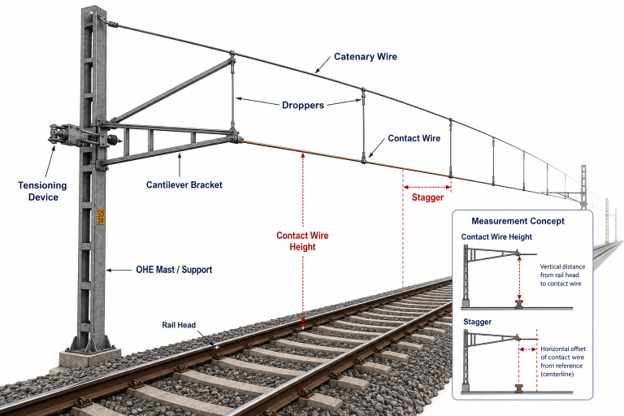
OHE stands for Overhead Equipment. It is also called over head line or catenary. It is the system of wires that carries electric power from the substation to the train’s pantograph.
Main parts of an OHE system:
- Catenary wire, the top wire that supports the system, strung between masts
- Contact wire, the wire the pantograph actually touches to draw power
- Droppers, small vertical wires that connect catenary wire to contact wire and keep the height steady
- Cantilever assembly, the bracket at each mast that holds everything up
- Tensioning device, equipment that keeps wire tension steady even when temperature changes
The whole system stays under tension all the time. It must keep a fixed distance from the rail below, on every curve, slope, and temperature change through the year.
Why Height and Stagger Matter Most
Height is the distance from the rail head up to the contact wire.
Stagger is how far the contact wire moves left and right of the track centre. This zig-zag pattern is done on purpose, so the pantograph’s carbon strip wears evenly instead of digging a groove in one place.
Both sound simple. Both cause serious problems if they go wrong.
If height is too low or too high, the pantograph does not press against the wire correctly. Contact becomes uneven. Wear speeds up. In bad cases, the pantograph can lose contact with the wire, or hit it too hard and damage both.
If stagger goes wrong, wear builds up at one spot on the pantograph strip instead of spreading evenly. Over time this can wear through the strip. In the worst case, the pantograph horn catches the wire and pulls it down. This is called a dewirement. It can take down wire across a long stretch and take hours to fix.
A rail defect usually builds up slowly. There is time to catch it before the next inspection. An OHE fault can cause a sudden failure that stops trains right away. This is why height and stagger checks need to be treated as safety-critical work, not routine paperwork.
A Closer Look: Key OHE Parameters
| Parameter | What It Means | Method Used | Why It Matters |
|---|---|---|---|
| Height | Vertical distance from rail head to contact wire | Laser gauge, manual pole/tape, recording car | Wrong height causes uneven contact force, faster wear, possible loss of contact |
| Stagger | Side-to-side offset of contact wire from track centre | Laser gauge scale, manual sighting, recording car | Wrong stagger causes wear at one spot, risk of dewirement |
| Contact wire wear | Loss of copper thickness on the contact wire | Wear gauge, visual inspection, recording car | Worn wire has less current-carrying capacity and can break under tension |
| Dropper spacing | Distance between droppers along a span | Manual measurement, visual check | Uneven spacing lets the wire sag between supports |
| Wire tension | Force applied to keep the conductor taut | Tension gauge, checked at tensioning device | Low tension causes sag and bounce; high tension increases wire stress |
(Exact tolerance figures for each parameter should be checked against the current RDSO specification for the section in question, since these can vary by speed class and get revised over time.)
How OHE Geometry Is Measured
Manual method. For many years, engineers checked height and stagger using a pole, tape, and eye sighting from a ladder or tower wagon. This works, but it is slow. The result also depends on how careful and experienced the person doing the check is.
Laser height and stagger gauge. A modern folding laser gauge lets the operator take a reading while standing at track level. The laser sits at eye height, with a viewing prism, so the operator sees the wire and the laser marker together, even in bright sunlight. Height shows up directly on the display. The reading already adjusts for the offset between the laser and the ground, so no extra calculation is needed on site. Stagger is read off a marked scale on the gauge’s side beam.
Recording cars. For checking a whole zone or route, special vehicles run under the wire and record height and stagger continuously, often along with wire wear and contact force. This gives a full profile of the route instead of single-point checks. These are usually used for big scheduled surveys, while laser gauges handle the regular spot checks in between.
With the Right Instrument vs Without: A Direct Comparison
This table compares a manual measurement approach against using a purpose-built laser gauge like the PIE-ABT 4640.
| Factor | Manual Method (pole, tape, sighting) | With PIE-ABT 4640 Laser Gauge |
|---|---|---|
| Time per span | Around 4 to 5 minutes | Around 1 minute |
| Operator position | Often needs a ladder or tower wagon | Standing position at track level |
| Reading calculation | Manual offset calculation needed on site | Height shown directly, offset already adjusted |
| Weather dependency | Harder to read in bright sun or low light | Built to read clearly even in bright sunshine |
| Consistency across operators | Depends heavily on the individual’s skill | Same clear reading method for every operator |
| Crew size needed | Often two or more people | Can usually be done by one trained person |
| Portability | Pole and tape are simple but bulky over long stretches | Folds flat, lightweight, easy to carry across many spans |
| Training time for new staff | Longer, since accuracy depends on experience | Shorter, since the display gives a direct reading |
| Data for RDSO documentation | Manual logging, higher chance of transcription error | Direct reading reduces recording errors |
| Best suited for | Very occasional checks, low budget | Regular inspection cycles across a zone |
The bigger the network you are responsible for, the more this time and consistency gap adds up. Multiply the time saved across hundreds of spans in a single possession window, and the laser gauge becomes the difference between finishing on schedule and falling behind.
Here is the same time comparison in chart form:
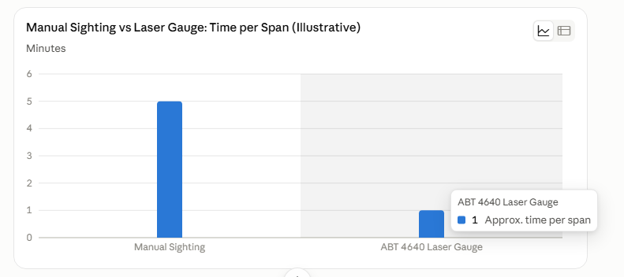
(These figures are illustrative, meant to show the relative time saved.)
Region by Region: The Job Is Not the Same Everywhere
OHE work on North Western Railway’s stretches through Rajasthan is not the same job as OHE work on Konkan Railway or NFR. A few things worth keeping in mind by region:
- Rajasthan and desert sections (North Western Railway, Jaipur zone). Summer heat above 45°C and blowing sand put real stress on instrument optics and electronics. Equipment that works fine in a lab needs to hold up here too.
- Konkan Railway and the western coast. Monsoon humidity and salty air speed up corrosion on OHE hardware. This means more frequent checks are worth the effort, not fewer.
- Northern Railway and North Central Railway (Delhi, Prayagraj). Winter fog cuts visibility badly for manual sighting. This is exactly where a laser gauge’s ability to read clearly in low visibility earns its place.
- Southern Railway and hill sections (Nilgiri and Konkan ghats). Dense curves mean stagger tends to drift faster and needs closer attention than on straight, flat track.
- Northeast Frontier Railway (Guwahati). Heavy monsoon terrain and harder access to remote sections make it worth completing more checks per possession window, instead of planning repeat visits.
- Dedicated Freight Corridor sections (Eastern and Western DFC). Higher speeds and heavier loads mean tighter tolerance. There is less room for measurement error here than on conventional lines.
An instrument that looks good on paper for “all of India” is not always the one that performs well in every one of these conditions. Field durability matters as much as accuracy on a datasheet.
Inspection Frequency: Conventional vs High Speed Sections
As line speed goes up, the allowed tolerance for OHE geometry gets tighter. A small deviation that is not a problem on a conventional passenger line becomes a real issue at higher speeds and on DFC sections with heavier, more frequent trains. Inspection frequency and the acceptable deviation range should be set based on the section’s speed class and traffic load, not applied the same way across an entire zone. Always check the current RDSO specification for the relevant line, since these values do get revised.
From Measurement to Maintenance Planning
The real value of height and stagger data is not any single reading. It is the trend over time. Zones that log measurements properly, instead of treating each check as a simple pass or fail, can find out which spans, curves, or structures are drifting out of tolerance faster than others. This lets them schedule a fix before it turns into a service problem. It is the same condition-based maintenance approach already used in track and wheel work, now applied to OHE.
Meet the PIE-ABT 4640: Laser Height & Stagger Gauge
The ABT 4640 is a purpose-built instrument for exactly this job. Here is what makes it useful for daily fieldwork:
Standing-position measurement. No need to climb a ladder or use a tower wagon for a routine check. The operator takes the reading standing at track level, which saves time and reduces safety risk on site.
Eye-level laser with viewing prism. The laser sits at eye height, and a 90-degree viewing prism lets the operator see the target cable and the laser marker at the same time. This works well even in bright sunshine, a real advantage across most of India for a large part of the year.
Direct height reading. The rail head to contact wire height is shown on an LCD display. The value is already adjusted for the offset between the laser position and the ground, so the operator does not need to do any extra math on site. This cuts down on calculation errors, especially useful for newer field staff still learning the job.
Clear stagger scale. Cable stagger is shown on a marked scale on the gauge’s side beam, giving a quick and repeatable reading.
Folding, lightweight design. The horizontal beam folds flat against the side beam for storage and transport. This matters a lot when a crew needs to carry the gauge across many spans in a single shift, sometimes over rough or remote terrain.
Available for both gauges. The instrument is available for Broad Gauge (BG) and Standard Gauge (SG), covering the different track types used across Indian Railways and metro networks.
(For exact technical specifications like measurement range and accuracy class, please refer to the current PIE-ABT 4640 datasheet before including numbers in the published version, since specifications can be updated.)
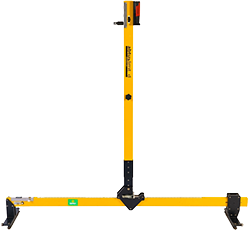
Fig. LASER HEIGHT & STAGGER GAUGE MODEL ABT4640
Why This Matters More for Indian Engineers
A few reasons this instrument fits Indian railway conditions specifically, not just railway work in general:
- Built for tender and audit needs. PIE instruments come with ISO/NABL calibration certificates and RDSO-compliant documentation, which matters directly for GeM portal purchases and open tender submissions.
- Handles India’s range of climate. From Rajasthan’s desert heat to Konkan’s monsoon humidity to North India’s winter fog, the same instrument needs to perform reliably across very different conditions within one country. Not every imported gauge is tested for this range.
- Faster training for junior staff. Many field teams include newer engineers and SSE-level staff who are still building experience. A direct digital reading, without on-site calculation, means less room for error and shorter training time compared to manual sighting methods.
- Pan-India service support. Paragon has dedicated service and application engineers who support customers across all 19 railway zones, both online and in person. Spare parts and calibration support do not have to come from far away.
- One-person operation. Where manual sighting often needs two people working together, the ABT 4640 is designed so one trained operator can complete the check confidently. That matters when possession windows are short and crew time is limited.
About Paragon Instrumentation Engineers
Paragon Instrumentation Engineers Pvt. Ltd. (PIE), headquartered in Roorkee, Uttarakhand, has designed, manufactured, and supplied precision measurement instruments for the Indian and global railway sector since 1959.
Over six decades of field experience across India’s 19 railway zones has shaped instruments built for exactly the kind of conditions covered in this guide.
All PIE instruments come with ISO/NABL traceable calibration and RDSO-compliant documentation( provided RDSO specs exist ), backed by pan-India service support.
Closing Thought
Track and wheel measurement usually get more attention in railway maintenance discussions. Rail wear and wheel defects are easy to see and easy to understand. OHE geometry is less visible, right up until it fails, and when it fails, it stops trains completely. As electrification keeps growing across the network, getting height and stagger measurement right, consistently, region by region, deserves to be treated as core infrastructure work, not an afterthought to track maintenance.